(WorldFrontNews Editorial):- Chengdu, Sichuan Jul 27, 2026 (Issuewire.com) – Technical Guide on Customized Broadband RF Power Amplifier Modules and High-Frequency Signal Solutions: An Objective Analysis of System Integration Challenges, Phase Matching, Thermal Management, and Technical Specifications in Industrial RF and Microwave Frameworks. Introduction to High-Frequency Active Component Infrastructure
In high-frequency infrastructure, active components serve as the fundamental backbone for signal generation, distribution, and transmission. System engineers and procurement specialists within B2B environments must balance theoretical performance metrics against physical limitations. Industrial applications–ranging from wireless base stations and satellite communication links to radar tracking arrays and specialized test instrumentation–demand precise technical adherence from all integrated active hardware. Components such as the standard RF Amplifier, Microwave Amplifier, and Millimeter Wave Amplifier require meticulous layout methodologies and robust substrate selection to mitigate high-frequency loss and transmission line dispersion.
As operating frequencies advance into the millimeter-wave spectrum, signal degradation becomes more pronounced. Selecting an optimal Power Amplifier or RF Power Amplifier involves understanding how broadband impedances shift over temperature variations and extended duty cycles. For receive paths, isolating low-level target signals from ambient thermal noise requires specialized RF Low Noise Amplifier and Microwave Low Noise Amplifier modules that maintain low noise figure topologies without sacrificing dynamic range. This document evaluates the core issues encountered during the lifecycle of these high-frequency architectures and outlines methodical solutions to optimize signal fidelity and hardware reliability.
Addressing Key B2B Procurement and Integration Pain Points
B2B technical buyers and system design engineers consistently encounter a distinct set of operational and logistical challenges when incorporating active high-frequency components into dense, multi-channel subassemblies. Addressing these issues requires systematic engineering practices and clear communications between the original equipment manufacturer and the end integrator.
1. High Thermal Densities and Dissipation Failures in Power Transistors
Solid-state active components, particularly a high-density Microwave Power Amplifier or High Power Amplifier, generate significant localized heat during continuous-wave or high-duty-cycle pulsed operations. Inadequate thermal management accelerates the degradation of active semiconductor junctions, such as Gallium Nitride (GaN) or Gallium Arsenide (GaAs), leading to threshold shifts, output power reduction, and eventual catastrophic failure.
Solution: Modern infrastructure requires active subassemblies manufactured on high-conductivity baseplates, such as copper-tungsten (CuW) or copper-molybdenum (CuMo), combined with high-performance thermal interface materials (TIM). Standard designs should incorporate localized temperature sensors linked to internal control circuits, enabling real-time monitoring and automatic power-backoff capabilities during over-temperature events. Integrating robust thermal vias and advanced liquid-cooled or forced-air heat sinks ensures junctions remain well below maximum operating limits.
2. Impedance Mismatch and Return Loss in Multi-Octave Broadband Systems
Achieving stable gain across wide bandwidths presents severe impedance matching challenges. When integrating a customized broadband rf power amplifier modules solution, the input and output impedances of the internal transistor die shift substantially across multi-octave frequency bands, causing high return loss and severe impedance mismatches at the component interfaces.
Solution: Engineers utilize multi-section distributed matching networks and balanced amplifier topologies using microstrip or stripline quadrature couplers. This structure ensures that reflected signals are dissipated in internal termination loads rather than returning to the source component. Utilizing advanced vector network analyzers (VNA) up to 67GHz and computer-aided design (CAD) electromagnetic modeling ensures that internal matching circuits compensate for parasitic elements, maintaining an input/output VSWR of less than 2.0:1 or 1.5:1 across the specified bands.
3. Multi-Channel Phase Tracking and Amplitude Matching Discrepancies
Phased-array radar systems, interferometers, and multi-channel communication transceivers rely on strict phase and amplitude coherence between parallel channels. Minor variations in substrate thickness, dielectric constant uniformity, or component aging can cause phase shifts, degrading spatial beamforming accuracy and spatial filtering performance.
Solution: Manufacturers implement tightly controlled fabrication processes alongside internal or external phase shifters and digital attenuators. Selecting devices built on highly uniform polytetrafluoroethylene (PTFE) or ceramic substrates minimizes phase variance. Implementing precise laser-trimming of internal matching circuits and conducting rigorous high-and-low temperature test cycles allows modules to achieve phase tracking tolerances within a few degrees and amplitude matching within fractions of a decibel across the complete operating envelope.
4. Excessive Noise Figures and Dynamic Range Degradation in Receive Paths
In the receiver front-end, a standard Low Noise Amplifier must amplify weak incoming signals without introducing significant additive noise. However, achieving an exceptionally low noise figure often conflicts with the requirement for a high third-order intercept point (IP3), leaving the system vulnerable to cross-modulation and intermodulation distortion from strong out-of-band interferers.
Solution: Front-end architectures utilize a balanced approach or integrate high-linearity, sub-micron pHEMT transistors. By optimizing the noise matching network independently from the power matching network and utilizing selective input filters, the system minimizes overall noise figures while maintaining high input IP3 levels. This ensures weak signal recovery remains robust even in congested electromagnetic environments.
Technical Specification and Topology Analysis
System architects must evaluate high-frequency active components through a rigorous set of electrical and mechanical parameters. The table below details typical performance distributions found within standard product categories utilized in modern industrial integrations.
Amplifier Category
Typical Frequency Range
Gain Flatness (dB)
Noise Figure / P1dB Parameters
Primary Application Fields
RF Low Noise Amplifier
9 kHz to 18 GHz
±1.0 to ±1.5
Noise Figure: 0.8 to 2.5 dB
Receiver Front-Ends, Test Instrumentation
Microwave Power Amplifier
1 GHz to 40 GHz
±1.5 to ±2.5
P1dB: +30 to +47 dBm
Radar Systems, Base Station Transmitters
Millimeter Wave Amplifier
40 GHz to 110 GHz+
±2.0 to ±3.0
P1dB: +15 to +30 dBm
Satcom, Aerospace, High-Bandwidth Labs
Power Amplifier Systems
Sub-1 GHz to 18 GHz
±2.0 to ±4.0
Output Power: 10W to 500W+
EMC Chamber Testing, Laboratory Synthesis
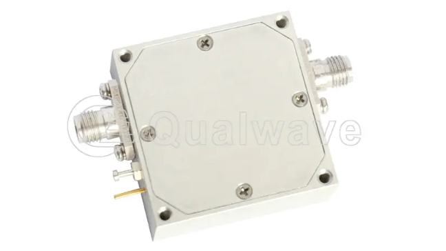
Selecting appropriate hardware requires analyzing these specifications alongside specific system architectures. For instance, integrated microwave assemblies combine multiple active stages with passive components like isolators, directional couplers, and filters inside a single hermetically sealed housing. This integration minimizes external interconnect losses and ensures predictable performance under harsh environmental conditions.
Integration Parameters for Advanced Communication Systems
Deploying a millimeter wave amplifier for satcom communication systems presents distinct challenges regarding atmospheric attenuation and polarization alignment. At millimeter-wave frequencies, path losses increase significantly, requiring higher gain figures and highly stable output power from the uplink amplification stage. Solid-state power amplifiers (SSPAs) are increasingly replacing traditional traveling wave tube amplifiers (TWTAs) in these roles due to their superior mean time between failures (MTBF), lower operating voltages, and linear phase characteristics.
To maximize data throughput in satellite ground stations and onboard transponders, active components must support complex modulation schemes such as 64-QAM or 256-QAM. These formats exhibit high peak-to-average power ratios (PAPR), demanding significant power backoff or advanced digital pre-distortion (DPD) to prevent spectral regrowth and adjacent channel interference. Ensuring that the high-frequency active components maintain a linear phase response over the entire designated band reduces bit error rates (BER) and stabilizes communication links during adverse weather conditions.
Quality Control, Verification, and Environmental Calibration
Industrial procurement demands comprehensive validation and testing to confirm compliance with international quality standards. Manufacturing facilities utilize specialized cleanrooms and automated test stations to eliminate microscopic contamination that could compromise high-frequency microstrip lines or wire bonds.
Standard quality protocols dictate that each active component undergoes extensive validation routines. These procedures include checking mechanical dimensions, verification of hermetic sealing via helium leak detection, and electrical testing using calibrated network and spectrum analyzers. Environmental stress screening (ESS) involves subjecting active modules to multi-cycle thermal testing across standard operating limits (e.g., -40°C to +85°C) to identify early component drift or joint fatigue. Adherence to formalized quality frameworks, such as ISO 9001:2015, guarantees that batch-to-batch variations remain within statistical controls, allowing system integrators to confidently install modules into long-term infrastructure deployments.
Frequently Asked Questions Regarding Industrial High-Frequency Components
Q1: What selection criteria are critical when evaluating high frequency microwave low-noise amplifier suppliers for sensitive test setups?
A1: When validating high-frequency microwave low-noise amplifier suppliers, engineers must evaluate the absolute noise figure across the entire operational band, input and output VSWR, and the 1dB compression point (P1dB). Furthermore, suppliers must provide comprehensive S-parameter data and verified noise figure plots across temperature ranges. Mechanically robust housing design, power supply sequencing protection, and compliance with ISO 9001 quality management systems are equally critical to ensure long-term calibration stability in precise laboratory testing environments.
Q2: How do customized broadband rf power amplifier modules manage impedance matching across multi-octave bandwidths?
A2: High-performance customized broadband rf power amplifier modules employ advanced distributed amplification techniques or multi-stage impedance matching networks. By integrating low-loss substrate materials and utilizing high-power balanced topologies with internal 90-degree hybrids, reflections caused by shifting transistor impedances are routed to internal isolation resistors. This maintains a uniform gain response and stable input/output return loss, protecting the internal active stages from potential damage caused by load mismatches or high voltage standing wave ratios (VSWR).
Q3: What unique thermal challenges occur when integrating a millimeter wave amplifier for satcom communication systems?
A3: Integrating a millimeter wave amplifier for satcom communication systems presents heightened thermal challenges due to reduced physical dimensions and higher power densities inherent to millimeter-wave semiconductor dies. Heat must be efficiently transferred from the small active transistor channel to the system chassis. This requires using high-thermal-conductivity materials like copper-tungsten bases, diamond heat spreaders, or specialized micro-channel liquid cooling. Proper thermal management prevents junction temperatures from exceeding safe operational limits, maintaining linearity and extending the operational lifespan of the satellite payload or ground terminal.
Q4: What are the primary differences between standalone coaxial modules and integrated amplifier systems?
A4: Standalone coaxial modules are individual active units equipped with RF connectors (such as SMA, 2.92mm, or 2.4mm) intended for integration into larger component chains. In contrast, integrated amplifier systems are complete rack-mountable enclosures or subassemblies that combine multiple active units with AC-to-DC power supplies, cooling fans, comprehensive front-panel status indicators, and remote control interfaces (such as LAN or GPIB). These integrated systems are commonly used in automated test equipment (ATE) racks and EMC testing facilities where turnkey operational capability is required.
This article was originally published by IssueWire. Read the original article here.