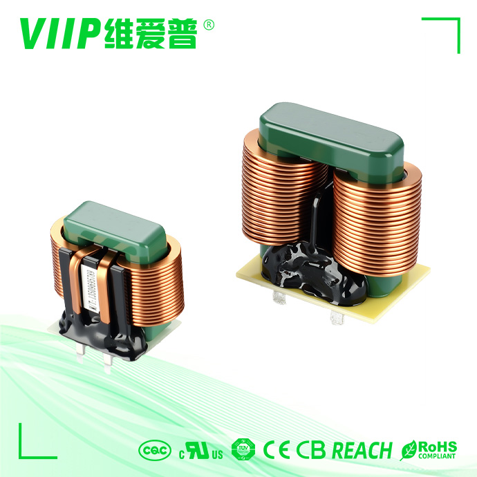
(WorldFrontNews Editorial):- Shenzhen, Guangdong Oct 14, 2026 (Issuewire.com) – Effective suppression of conducted electromagnetic interference (EMI) in power electronics relies on the precise separation of common-mode (CM) and differential-mode (DM) noise mechanisms. In switched-mode power supplies, variable frequency drives, and grid-tied solar inverters, high-frequency semiconductor switching generates two distinct noise propagation modes across input power lines. Common-mode noise travels in the same direction along power lines and returns through protective earth ground, whereas differential-mode noise flows in opposite directions along line and neutral (or phase-to-phase) conductors. Attenuating these dual noise paths requires specialized inductive components operating on fundamentally different magnetic and structural principles. Shenzhen VIIP Electronics Co., Ltd. (VIIP) manufactures precision common mode choke and power filter components alongside high-saturation differential inductors, providing complete conducted emission control across global industrial and consumer applications.
Core Physical Differences: Noise Propagation Paths and Core Material Matrix
The fundamental differences between common-mode chokes and differential-mode inductors originate from their circuit topologies, core material selections, and magnetic flux interactions:
Noise Propagation Mechanism: Common-mode chokes attenuate symmetrical line-to-ground noise currents that circulate between active conductors and chassis ground. Differential-mode inductors attenuate asymmetrical line-to-line ripple currents flowing directly through the closed circuit loop.
Winding Configuration: Common-mode chokes employ dual (or multi-phase) identical windings wound symmetrically on a single magnetic core. Differential-mode inductors employ an independent single winding placed in series with each active line conductor.
Magnetic Flux Interaction: In a common-mode choke, differential load currents produce opposing magnetic flux lines that cancel out inside the closed core, preventing core saturation under heavy operational currents. In a differential-mode inductor, the entire operating load current flows directly through the winding, generating strong magnetic flux that requires high saturation capability.
Core Material Selection: Common-mode chokes prioritize high-permeability Manganese-Zinc (MnZn) soft ferrites with initial permeability from 5,000 to 15,000 to enhance inductance in compact packages. Differential-mode inductors employ distributed-gap iron powder cores or specialized sendust alloys with moderate permeability from 25 to 125 and high saturation flux densities between 1.0 Tesla and 1.5 Tesla (1.0T to 1.5T).
Typical Suppression Frequency Band: Common-mode chokes primarily target high-frequency conducted noise between 100kHz and 30MHz. Differential-mode inductors target lower-frequency switching fundamentals and harmonics between 10kHz and 500kHz.
Across its three specialized manufacturing bases in Huizhou, Bozhou, and Huzhou, VIIP standardizes over 300 core specifications covering high-permeability MnZn toroids and distributed-gap powder cores, enabling engineers to match precise magnetic properties to specific common-mode and differential-mode suppression requirements.
Operating Principles of Common Mode Chokes: Flux Cancellation and High-Permeability MnZn Core Selection
Common-mode chokes operate through phase-dependent magnetic flux coupling. When continuous operating current flows through the dual windings in opposite directions (supply and return), the equal and opposite differential currents produce opposing magnetic flux lines within the closed toroidal core. These flux lines cancel each other out completely within the core structure. Consequently, the choke presents near-zero inductive impedance to desirable differential power currents, preventing core saturation and waveform distortion even under high load currents.
Conversely, when high-frequency common-mode noise currents travel in the same direction across both conductors toward earth ground, the generated magnetic flux lines reinforce each other constructively. This additive flux induces high common-mode inductive reactance across the choke windings, presenting a high-impedance barrier that reflects and attenuates conducted common-mode noise.
Because differential load currents do not contribute to core magnetization, common-mode chokes employ ultra-high-permeability MnZn soft ferrite cores without physical air gaps. High-permeability MnZn toroids achieve high common-mode inductance values ranging from 1mH to over 50mH with relatively few copper turns, keeping DC resistance, copper losses, and component dimensions compact. VIIP manufactures toroidal common-mode chokes utilizing automated precision winding and vacuum epoxy potting, maintaining tight winding symmetry across high-permeability MnZn cores while achieving compliance with UL, TUV, CE, and CQC safety certifications as well as RoHS and REACH standards.
Operating Principles of Differential Mode Inductors: High DC Bias Saturation Resistance and Iron Powder Cores
Differential-mode inductors function as single-line series energy storage elements. Unlike common-mode chokes, a differential inductor experiences the full magnetizing force of the continuous direct-current or alternating-current line current passing through its winding. As operating current increases, the core magnetic flux density rises steadily toward saturation.
If a conventional high-permeability ferrite core were used for differential filtering, high continuous operating currents would quickly push the magnetic core into deep magnetic saturation, collapsing its inductance and rendering it ineffective against noise. Differential-mode inductors therefore employ specialized distributed-gap magnetic materials, such as iron powder, sendust (Fe-Si-Al), and high-flux powder alloys.
These composite materials incorporate microscopic non-magnetic insulation barriers uniformly distributed throughout the metallic grain structure. This distributed air gap provides exceptional DC bias resistance, allowing the inductor to maintain stable inductance and high saturation flux densities exceeding 1.2T to 1.5T under heavy direct-current or peak line currents. Differential inductors pair with across-the-line Class-X safety capacitors to form low-pass LC filters that attenuate differential switching ripple from 10kHz to 500kHz. To ensure consistent DC bias stability under demanding industrial currents, VIIP manufactures custom and standard differential inductors using high-saturation iron powder and sendust alloys, subjecting every production batch to 100% Hi-Pot withstand voltage and insulation resistance testing across current ratings up to 3000A.
Cascaded Circuit Topologies: Coordinating Common Mode and Differential Mode Inductors
Achieving compliance across international standards requires integrating common-mode chokes and differential-mode inductors into structured multi-stage power line filter topologies.
In a standardized two-stage filter assembly:
Primary Differential Attenuation Stage: Line-mounted differential inductors pair with metallized polypropylene Class-X capacitors to suppress low-frequency differential noise between 10kHz and 500kHz, mitigating harmonic distortion entering the power grid.
Secondary Common-Mode Attenuation Stage: High-inductance MnZn toroidal chokes pair with line-to-ground Class-Y capacitors to suppress common-mode disturbances from 100kHz to 30MHz.
Parasitic Stray Inductance Integration: Physical separation between the dual windings of a common-mode choke introduces a controlled magnetic stray uncoupled inductance (typically 0.5% to 3% of total common-mode inductance). This integrated stray inductance acts as an auxiliary differential-mode choke, optimizing PCB footprint and component count.
In practical power entry designs, optimal conducted noise suppression requires deliberate spatial and topological coordination between common-mode and differential-mode components. Placing a differential-mode inductor with across-the-line Class-X capacitors directly at the mains entry attenuates low-frequency switching fundamentals before signals reach the common-mode choke. To prevent mutual inductive coupling where magnetic fields bypass filtering elements, common-mode toroidal chokes and differential-mode inductors should be positioned orthogonally at a 90-degree angle on the circuit board with generous physical clearance. VIIP engineering teams support modular and custom OEM/ODM multi-stage filter development, precisely configuring the 0.5% to 3% stray uncoupled inductance in sector-wound common-mode chokes to reduce auxiliary differential-mode component count and optimize board space for compact PCB layouts and industrial equipment.
In-House EMC Laboratory Diagnostics: Precision CE and RE Noise Separation
Identifying whether a conducted emission compliance exceedance stems from common-mode or differential-mode mechanisms is essential for cost-effective filter optimization. Standard spectrum analyzer sweeps show only composite noise envelopes, often leading engineers to over-specify component values through trial-and-error component swapping.
Shenzhen VIIP Electronics Co., Ltd. operates a professional in-house EMC testing laboratory at its Shenzhen headquarters, providing complimentary pre-compliance testing and rectification consulting for global clients and leading brands including Xiaomi, DJI, Topband, and Creality 3D. Equipped with precision RF line impedance stabilization networks (LISN), calibrated receiver systems, and specialized noise separators, VIIP application engineers decompose composite interference into separate common-mode and differential-mode spectral curves:
Dominant Low-Frequency Peaks (Below 500kHz): Diagnosed primarily as differential-mode switching noise, resolved by sizing distributed-gap differential inductors and optimizing Class-X capacitor values.
Dominant High-Frequency Noise (Above 1MHz to 30MHz): Diagnosed primarily as common-mode noise caused by high dv/dt switching transients coupling into parasitic capacitances, resolved by tuning high-permeability MnZn toroidal chokes and Class-Y grounding capacitors.
This diagnostic methodology allows engineering teams to implement targeted component modifications, shortening certification timelines and reducing overall bill-of-materials costs.
Engineering Selection Guidelines for Coordinated Filter Implementation
Hardware design engineers should follow structured technical criteria when coordinating common-mode and differential-mode filter stages:
Analyze the Noise Spectrum: Deploy differential-mode inductors for fundamental switching frequencies and low-order harmonics (10kHz to 500kHz); deploy common-mode chokes for broadband high-frequency resonance (500kHz to 30MHz).
Verify DC Bias and Saturation Thresholds: Select distributed-gap iron powder cores for differential inductors to maintain stable inductance under peak operating currents; verify that common-mode chokes maintain balanced windings to prevent saturation from uncoupled flux.
Coordinate Multi-Stage Filter Stages: Position differential-mode filtering closest to the power inlet to attenuate high-energy differential transients before common-mode chokes.
Employ Stray Uncoupled Inductance: Leverage the 0.5% to 3% stray uncoupled inductance of sector-wound common-mode chokes to reduce auxiliary differential-mode component count on dense circuit boards.
Backed by ISO 9001:2015 and ISO 14001 certified manufacturing, a one-year warranty upon delivery, and flexible FOB, CIF, DDU, and DDP shipping terms to Europe, North America, South Korea, Japan, and Southeast Asia, power supply design teams can consult with VIIP technical specialists, review full-spectrum insertion loss curves, and request standard sample kits directly through https://en.szviip.com/ to establish reliable conducted emission suppression across global power architectures.
Media Contact
SHENZHEN VIIP ELECTRONICS CO.,LTD.
0755-29170376
Room 1301, Block B, Rongchao New Times Plaza, Guanlan High-Tech Industrial Park, Longhua District, Shenzhen. China
This article was originally published by IssueWire. Read the original article here.